[Motor control] Short introduction to sensorless field oriented control
In hall sensor based 6-step control, rotor position is measured using hall sensors, and the angle between stator and rotor flux varies from 60 to 120 degrees. There are 2 significant improvements in sensorless-FOC drives. First, the rotor position is estimated with better precision. Hall sensors output rotor positions at 60 degrees intervals only. But FOC drives obtain rotor positions at typically 2-5 degree intervals. Second, the 6-step commutation can generate only a fixed set of magnetic fields. FOC drives can generate arbitrary magnetic fields in the motor.
These improvements enable the FOC drive to maintain the stator flux always orthogonal to rotor flux (note that maximum torque is produced when stator and rotor flux are orthogonal). This blog post provides a brief overview of how sensorless-FOC drives work. A brief introduction to 6-step control is covered here.
 |
|---|
| FOC visualization. The three currents Ia , Ib , Ic , together generate the stator field Bstator (orange arrow). The rotor field Brotor (green arrow) comes from the permanent magnets. The motor-drive controls Ia , Ib , Ic so that the stator field is perpendicular to rotor field. |
Motor control step 1 - estimate rotor position
In the absence of hall-sensors or other rotor position sensors, the back-emf generated in the winding by the rotor rotation can be used to calculate the rotor position. It helps to understand how the back-emf encodes the rotor angle. Then, the method to estimate the back-emf will be discussed.
Back-EMF encodes rotor position
The electro-motive-force (EMF) generated in the winding is equal to the rate of change of magnetic flux
e = -d(F)/dt
where F is the flux through the winding.
When a BLDC motor rotates, the flux generated by the permanent magnets moves through the winding and in the process an EMF is induced in the winding. This induced EMF is called back-emf. The back-emf induced in the 3-phase winding are generally a sinusoidal function of the rotor position and proportional to rotor speed. Further, the back-emf signals have a 120 degree phase difference from each other. The back-emf signals in the 3-phase provide sufficient information to infer the rotor position.
 |
|---|
| FEMM simulation of flux linkage when the rotor moves. The flux linkage values are processed to determine change in flux linkage. The change in flux linkage induces a voltage in the winding. Rotor angle can be calculated using the induced EMF in the three winding because at each rotor position the induced back-emf in the three winding are unique. |
The animation showed how the back-emf encodes the rotor position. So if the drive can measure the back-emf directly, the rotor position can be easily calculated. However, sensing the back-emf directly is not possible.
Why is it not possible to measure the back-emf directly in FOC drives ?
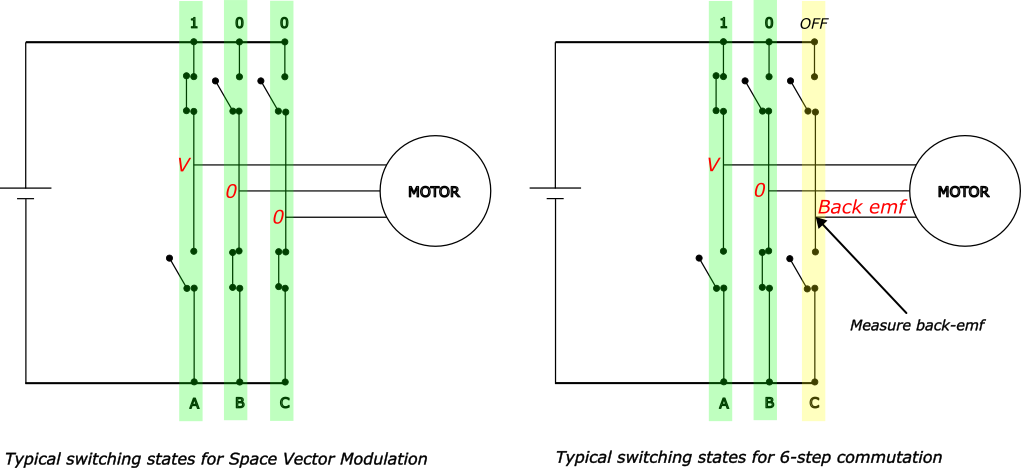
In many cases, back-emf can be measured directly for example in conventional 6-step commutation. In 6-step commutation, 2 of the 3 phase of the inverter are energized and the third phase is not energized. The back-emf generated by the motor can be directly measured in the un-energized phase of the inverted.
But FOC drives use space-vector-modulation read more about space vector modulation here. In space-vector-modulation, all the three phase of the inverter are energized at all times. So, the back-emf generated by the motor can not be measured.
 |
|---|
| The image shows the difference between 6-step switching and space-vector-modulation switching. In space-vector-modulation, all the three inverter phases are energized (either V or 0). In 6-step, only 2 of the 3 phases are energized. The back-emf generated in the motor phase appears at the un-energized inverter phase |
Estimating back-emf
Motor controllers use Digital Signal Processing (DSP) techniques to estimate the back-emf. These DSP techniques are also called Observers. This section provides a brief explanation of how back-emf is estimated with a simple example.
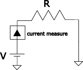
Suppose we have a resistance load, say 1 Ohm, connected to controlled voltage source and we measure the current through the load. If we apply 2V to the load, the current reading through the meter will be 2A.
 |
|---|
| Simple resistance load with current measurement through the load. If the resistance is 1 Ohm and 2V is applied at V, the current measurement will read 2A. |
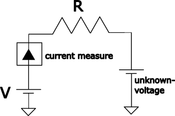
Now, we have another voltage source in the circuit with an unknown voltage value. If the controller applies the same 2V to the load and the current reads 1A. Since we know the resistance load, we can calculate the unknown voltage source value as 1V.
 |
|---|
| We can back calculate the value of the unknown voltage if we know the value of the resistance and the value of the applied voltage |
This technique can be extended to the 3 phase of BLDC motors.
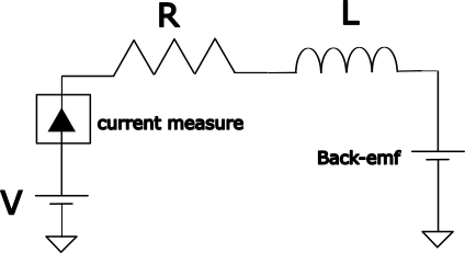
Instead of a resistance load, the motor winding is a series RL (resistance-inductance) load. And the unknown voltage is the induced back-emf. The back-emf cannot be calculated by simple algebra as in the previous example but requires the differential equation of series RL circuit.
 |
|---|
| back-emf estimation in one phase of the motor |
 |
|---|
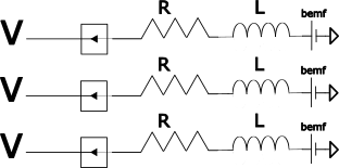
| back-emf estimation in 3 phase of the motor |
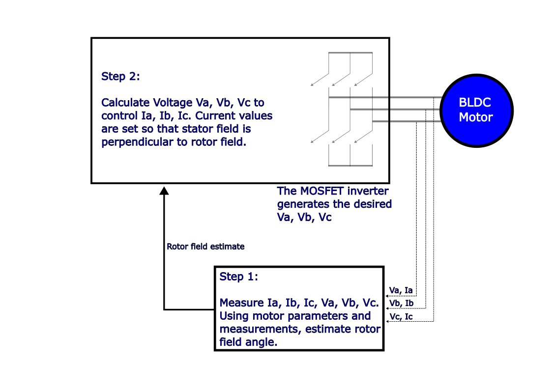
The controller uses the motor parameters like resistance and inductance along with the measured voltage and currents to estimate the back-emf. With the estimate of the back-emf, the rotor position can also be deduced.
Motor control step 2 - drive current through winding
After obtaining the rotor position, the next step is to ensure the stator flux generated is orthogonal to the rotor flux. Unlike 6 step control, vector controllers can generate stator flux in any arbitrary direction. This is achieved using space-vector modulation technique. Read more about space vector modulation here.
The controller sets the direction of the stator flux orthogonal to the direction of rotor flux (rotor position) and the magnitude of the stator flux is controlled by the magnitude of the current in the phase winding. The current controllers are generally PI (proportional-integral) controllers.
 |
|---|
| Step 1 and step 2 in sensorless FOC |
The previous discussions assumed the motor parameters are available to the controller. This may not be the case all the time. So most controllers have an in-built feature to estimate motor parameters. The motor parameters are necessary for tuning the current controllers as well as for measuring the back-emf. read more about the importance of motor parameters in this post
Also note that the controller estimates the induced back-emf to calculate the rotor position. A back-emf is induced only when the rotor is moving and generates a change in flux linkage in the winding. So when the rotor is not moving or when it is moving very slowly, the back-emf cannot be estimated and hence the rotor position is unknown. All sensorless motor controllers have a some startup technique to overcome this drawback. Read more about some of this techniques here..
Advantages of sensorless FOC
- sensorless drives are more reliable as there is no risk of rotor position sensor failure.
- A sensorless motor is also cheaper to manufacturer.
- FOC drives have a reduced torque ripple compared to 6-step drives.
- Flux weakening is possible in FOC drives. The motor can be driven to speeds higher than the rated speed.
- Efficiency is also higher in FOC drives.