[Motor control] 6 step commutation using hall sensors
This post describes the operation of 6 step control algorithm also called 6-step commutation. The 6-step algorithm is usually done with the help of hall sensors for rotor position feedback. The hall sensor states and the corresponding commutation table will be developed.
In a bldc motor, torque is generated by the interaction of two magnetic entities, stator flux and rotor flux. Current through the stator winding generate stator flux. Rotor flux is generated by the permanent magnets. The torque produced by the two interacting fields varies as a sine of the angle between them. So, maximum torque is generated when the two fields are orthogonal (90 degree) and zero torque is generated when the fields are aligned (0 degrees).
Note that 6-step commutation can also be implemented without hall sensor feedback. The idea behind the algorithm remains the same.
Hall sensor feedback for rotor position
Hall sensors are placed in the stator, facing the magnets on the rotor. For the hall sensors to generate valid states, they must be displaced 120 degrees electrical to each other.
 |
|---|
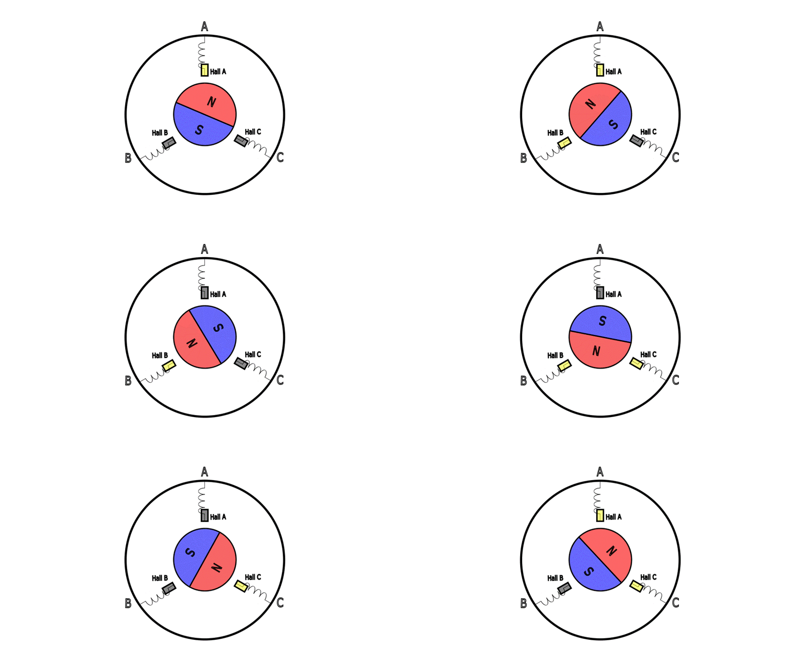
| Animation shows the hall sensors sensing the rotor north pole as the rotor rotates |
 |
|---|
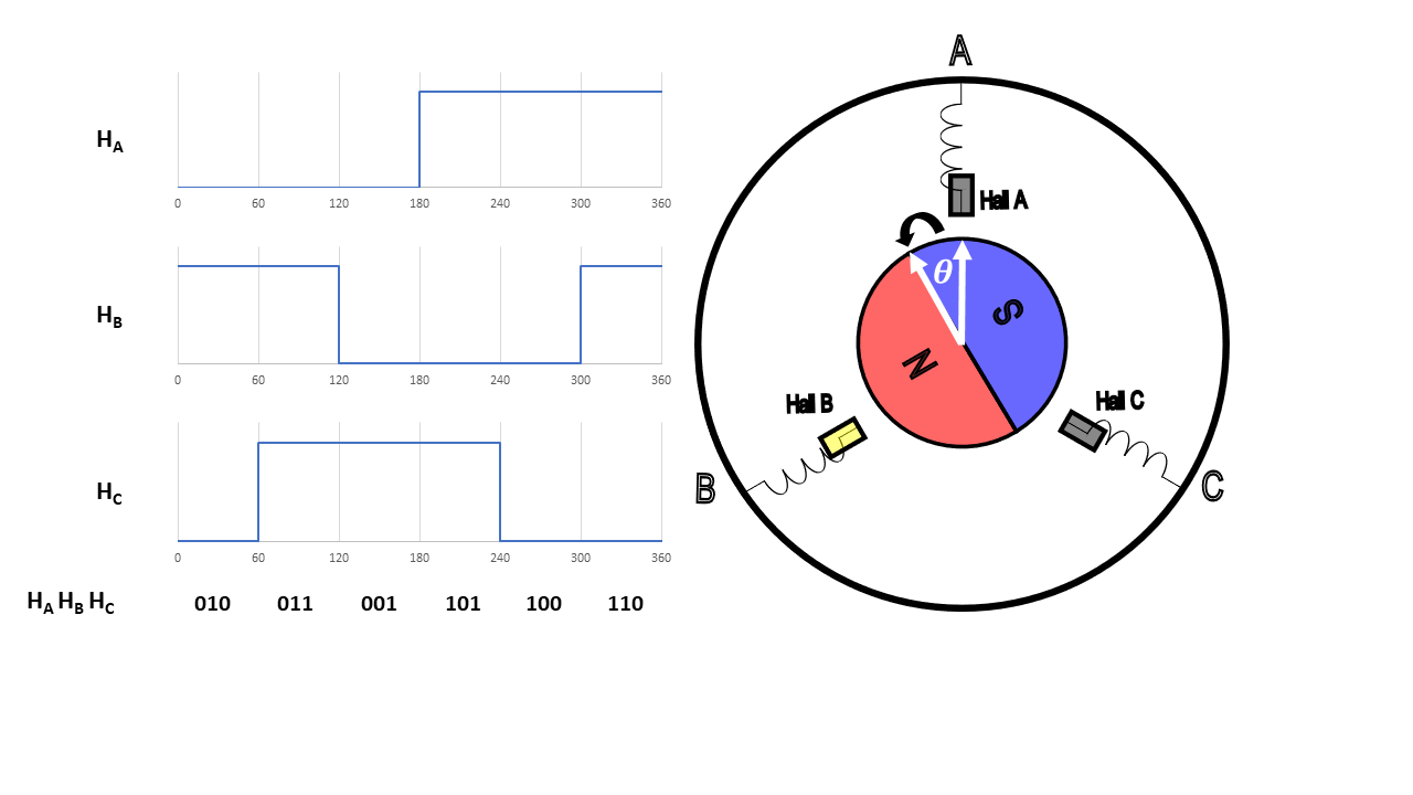
| The hall states as a function of rotor position. Based on the hall states HA HB HC the rotor position can be inferred |
As seen in the animation, hall sensors provide rotor position feedback every 60 degrees only.
In the example, the hall sensors are placed at the same location as stator winding. This is an important detail. If the hall sensors were placed somewhere else, the hall sequence HA HB HC will still be generated as long as the hall sensors are 120 degrees electrically displaced. But, the rotor position corresponding to the hall state will be different.
Stator flux in 6 step commutation
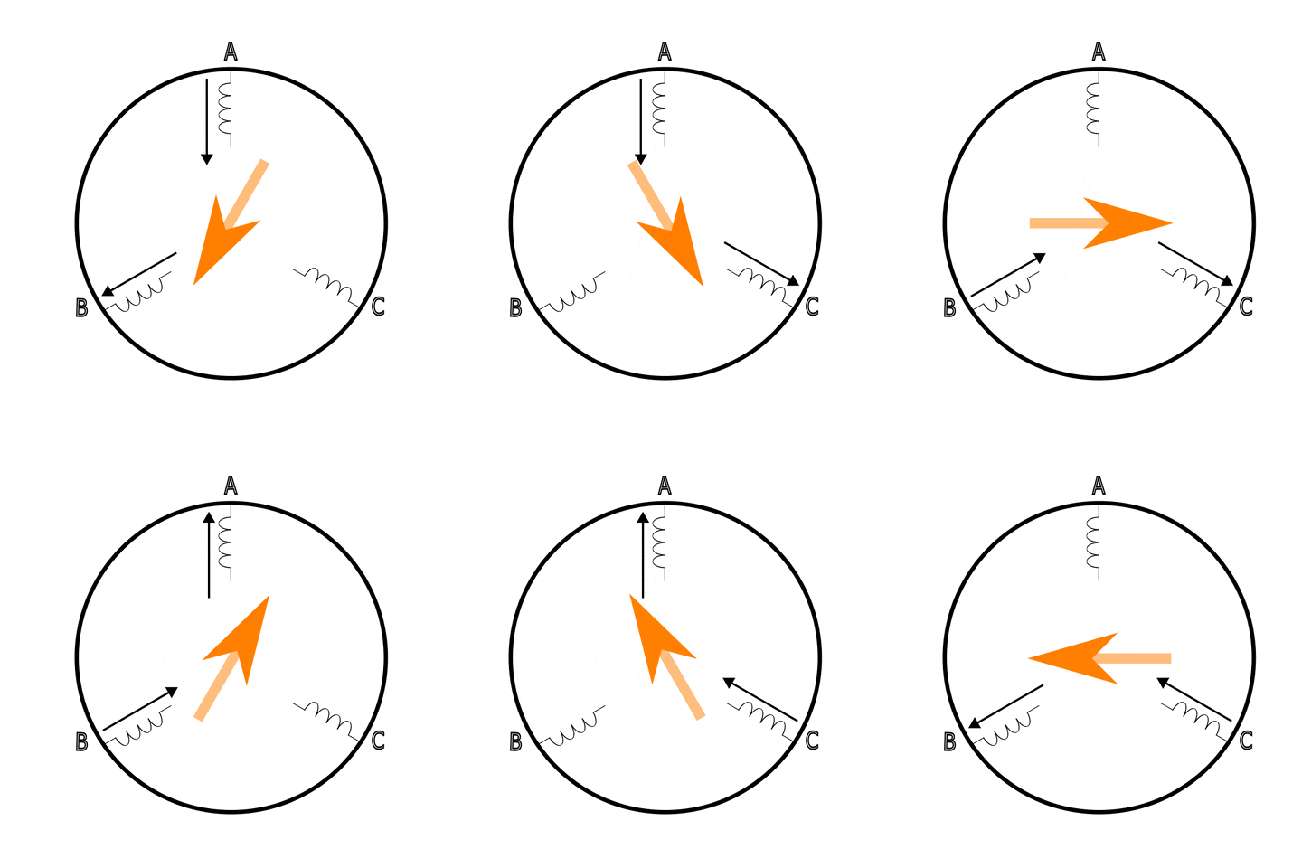
In 6 step commutation, one of the phase winding is energized, one of them is grounded, the third phase is floating. Thus, current flows into one winding, flows out of another winding, and the third winding is un-energized. The current flowing through the winding generates a flux. The magnitude of this flux depends on the magnitude of the current. The direction of the flux depends on which winding the current flows and in which direction (in or out).
This configuration is cycled through all the phases. The stator flux can be aligned to 6 different directions.
 |
|---|
| By energizing appropriate stator winding, the stator flux can be positioned to different angles. The black arrow represents the current flowing the winding and orange arrow represents the flux angle generated |
The 6 step control
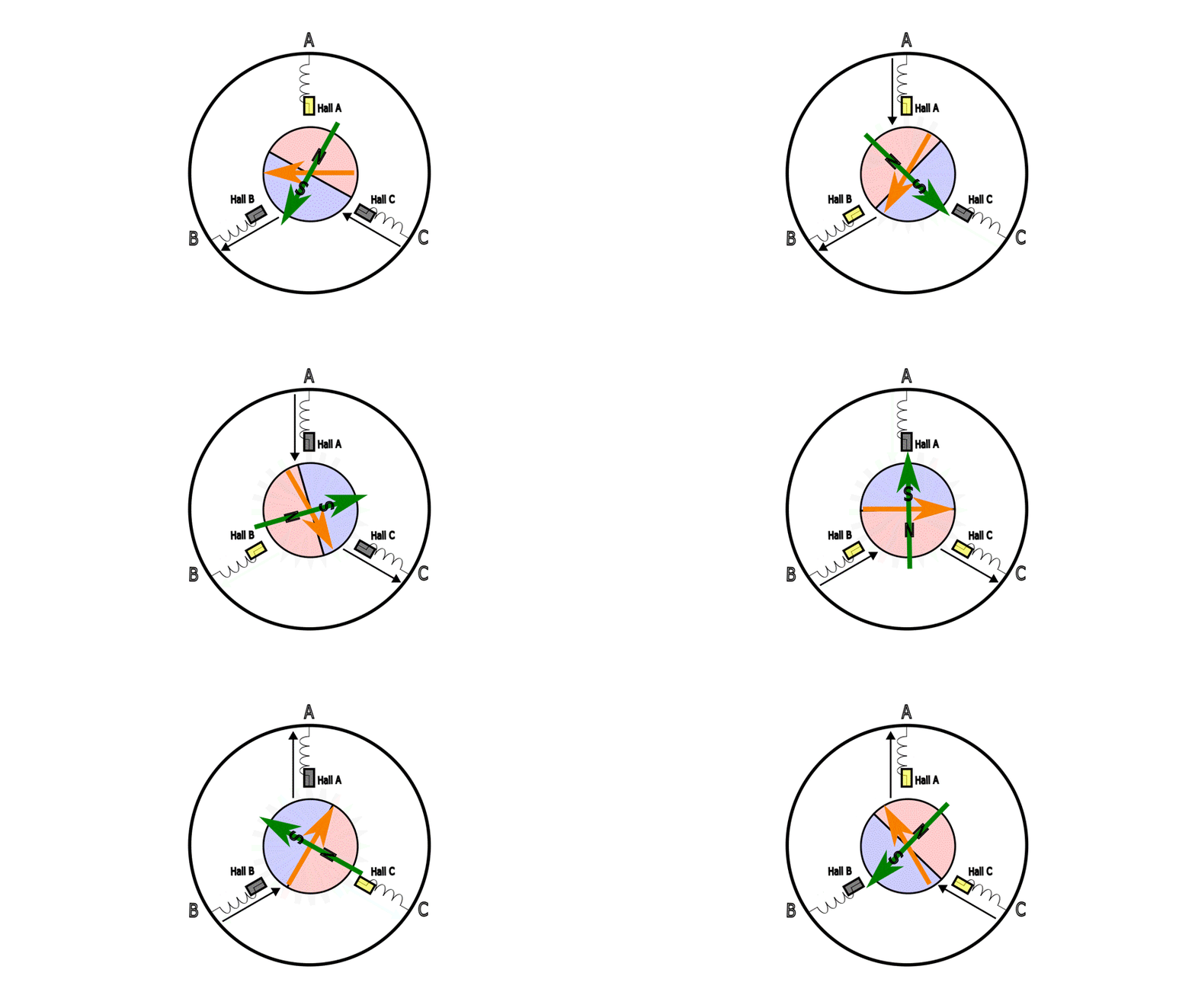
The goal of the commutation algorithm is to align the stator flux orthogonal to the rotor flux. The hall sensors provide the rotor position. The stator winding are energized based on the rotor position.
Based on the hall sensor states, a commutation table can be generated.
| HA HB HC | Stator voltage |
|---|---|
| 100 | C+ -> B- |
| 101 | C+ -> A- |
| 001 | B+ -> A- |
| 011 | B+ -> C- |
| 010 | A+ -> C- |
| 110 | A+ -> B- |
 |
|---|
| 6 step control visualized. The green arrow represents the rotor flux direction. The orange arrow is the flux generated by energizing the stator winding. The black arrows represent the current direction in the winding |
6 step control cannot ensure stator flux and rotor flux are orthogonal at all times. The angle between the two fields varies from 60 degrees to 120 degrees. This causes torque ripples because the torque generated varies as a sine of the angle.
Read how to work without hall sensors in this blog post on sensorless-FOC techniques.