[Motor control] space vector modulation explained
Space vector PWM (Pulse width modulation) is common technique used in the control of 3-phase AC motors. The space vector PWM enables smooth and efficient operation of the motor. This post will start with a quick introduction to space vector theory using an example. Then, the concept of voltage space vector PWM will be discussed.
Example of a space vector
An analysis of air gap MMF (magnetomotive-force) in a 3-phase rotating electrical machine is helpful to understanding space vector theory.
 |
|---|
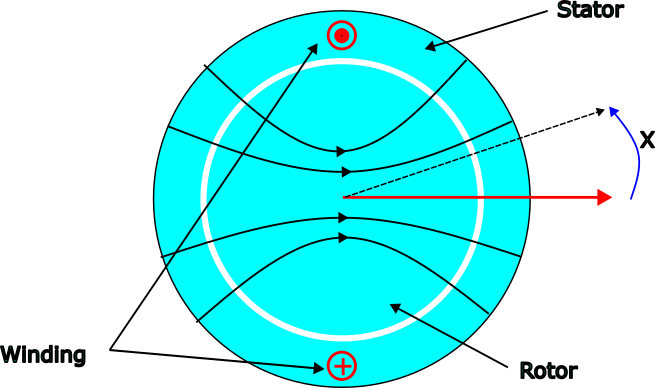
| 1 phase (phase A) is represented of a 3 phase machine. |
We assume an ideal electrical machine in the above picture. If the winding carries a constant current, an MMF is generated in the air gap. The direction of the MMF in the air gap is radial and the magnitude varies sinusoidal as a function of the angle x.
The air gap MMF due to phase A is given by
fa(x) = K.Ia.cos(x)
where K is constant dependent on machine design like winding pattern, stator/rotor materials etc and Ia is the instantaneous current in the winding A. The MMF distribution can be represented by a vector (red arrow) with its magnitude equal to the peak MMF value in the air gap and the direction as shown. This vector is an example of a space vector. The direction of this space vector fa is constant but the magnitude of the vector varies with the current Ia.
 |
|---|
| Winding A and its space vector. The direction of the space vector remains the same but the magnitude can be adjusted by current Ia. The animation shows the air gap MMF and the MMF space vector variation because of alternating current in the winding. This MMF is also sometimes called pulsating MMF |
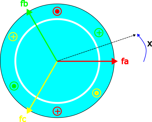
Similarly, the air gap MMF due to phase B and Phase C is given by
fb(x) = K.Ib.cos(x - 120)
fc(x) = K.Ic.cos(x + 120)
and the resultant MMF in the air gap due to all 3 phase is
f(x) = fa(x) + fb(x) + fc(x)
All 3 winding and their MMF space vectors are shown in the figure.
 |
|---|
| All 3 phase of the machine indicated in this picture with the corresponding space vectors displayed. Each space vector is 120 degrees from each other because each winding is 120 degree to each other in a 3 phase machine |
Now there are 3 vectors 120 degree to each other representing the MMF generated by each winding. If a 3 phase current is passed through the winding, the 3 space vectors magnitudes will vary proportional to the current. The vector sum of these space vectors results in a rotating space vector. The animation below shows the vectors fa, fb, fc, magnitude varying sinusoidal and the resultant vector sum f.
 |
|---|
| Each of the 3 space vectors magnitude varies sinusoidal along their axis but the sum of these vectors is a rotating vector (blue). This result can be verified using simple vector algebra (Thin line indicates axis and the thick line indicates the space vector magnitude) |
A rotating space vector implies a sinusoidal air gap MMF distribution with the MMF distribution moving along the air gap with time. This is called a rotating MMF and driving a 3 phase current to a 3 phase winding is a method to achieve it. We can verify this result in a simulation.
 |
|---|
| The animation on the left shows a FEMM (Finite Element Method Magnetics) simulation driving a 3 phase current in a 3 phase winding. The MMF distribution at all times is a sine wave and this sine wave moves. The blue arrow represents the changing angular position of the MMF space vector. In the right is the rotating vector animation as before. Together with the left and right animations, the rotating space vector and rotating air gap MMF can be visualized |
The rotating MMF in an electrical machine was observed in both the space vector analysis approach (represented by a rotating space vector) as well as through a FEMM simulation. This example shows that the analysis of air gap MMF in electrical machines can be performed by representing the air gap MMF as space vectors and performing vector operations on them.
Voltage as space vectors
The previous section explained about air gap MMF and introduced the space vector concept. The MMF space vectors are in accordance with a physical direction of MMF in the air gap. A space vector can also be defined for other quantities, like voltage, which do not have any physical direction.
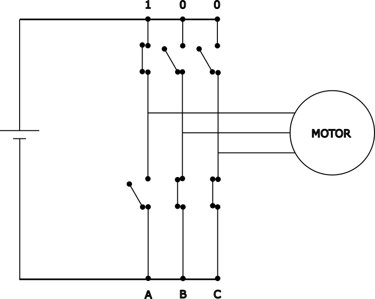
Most motor controllers use a 3 phase voltage-source-inverter (VSI) to supply power to the motor winding. VSI are switching devices and the output voltage for each phase can vary between positive and negative rails only. In each VSI leg (A,B, or C), either the top switch is ON (indicated by 1) or bottom switch is ON (indicated by 0). There are thus 8 different switching configurations that a VSI can generate. The switching configuration is represented by abc where a,b,c can be 0 or 1 indicating whether top or bottom switch is ON and a,b,c, represent the corresponding leg for phase A,B,and C.
 |
|---|
| 3 phase voltage source inverter (VSI) in switching state 100. When the top switch is ON, the leg is indicated as 1 and when bottom switch is ON, the leg is indicated as 0 |
We will represent the voltage across each of the 3 phase winding as space vectors. Further, these space vectors will be placed 120 degrees apart. Then, each of these 8 switching configuration can be assigned a space vector.
When the A phase is connected to the positive rail and phase B,C are connected to the negative rail, the voltage vector would be along the A phase axis. When A phase is connected to the negative rail and phase B,C are connected to the positive rail, the voltage space vector will be along negative A phase axis.
Since the machine is symmetric, this concept is applicable to phase B and phase C also, generating voltage space vectors along phase B axis, phase C axis, negative phase B axis, negative phase C axis.
 |
|---|
| All possible voltage space vectors that can be generated by VSI with the switching states indicated |
To operate a 3 phase machine with low torque ripple and good efficiency, the controller needs to generate a smooth rotating voltage space vector. The Space Vector PWM is a technique to generate smooth rotating voltage space vector using the 8 space vectors. By rapidly switching between discrete space vectors, we can generate a resultant space vector that is a time weighted vector sum of the 8 discrete space vectors.
Generating arbitrary voltage space vectors
The method to generate arbitrary voltage space vectors using the 8 available space vectors will be explored in this section. First, consider the case where the VSI switches between an active vector and a zero vector, 100 and 000. The duration for which the VSI stays at a space vector is sometimes called dwell time.
 |
|---|
| VSI switching between 2 different space vectors. The dwell time for each space vector is indicated and the resultant space vector is also shown. By varying the dwell time for each space vector, the resultant space vector can be modified. |
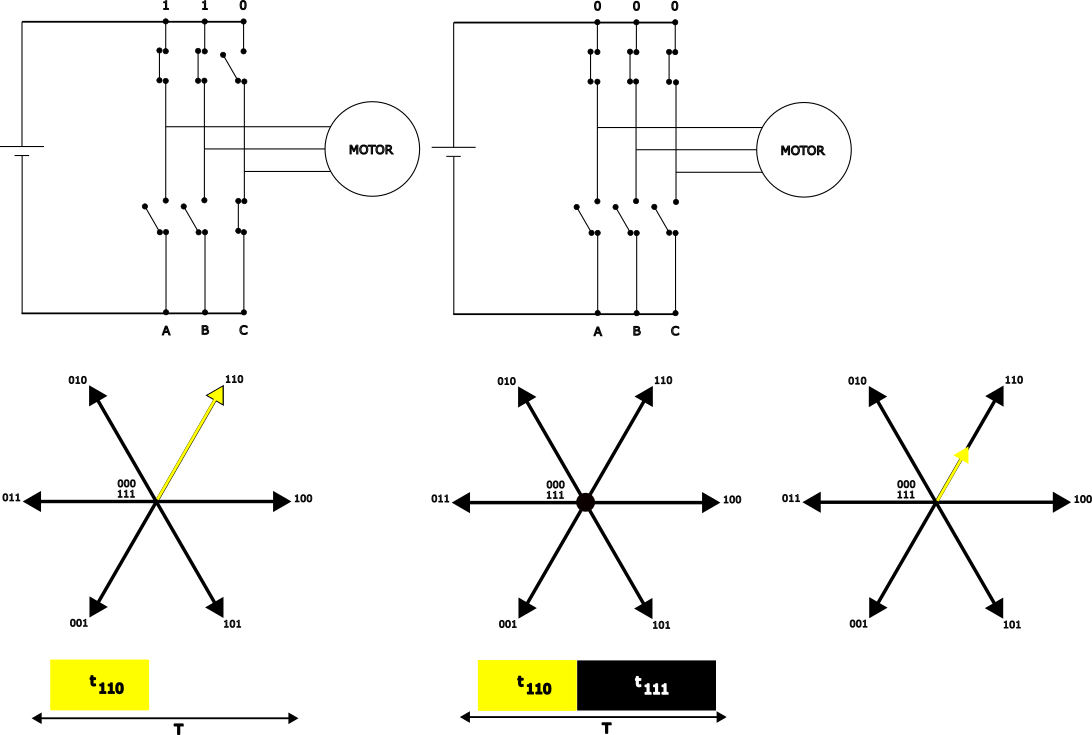
Similar to the previous example, the VSI can also switch between another active vector and zero vector, 110 and 111.
 |
|---|
| VSI switching between 110 and 111 space vectors. |
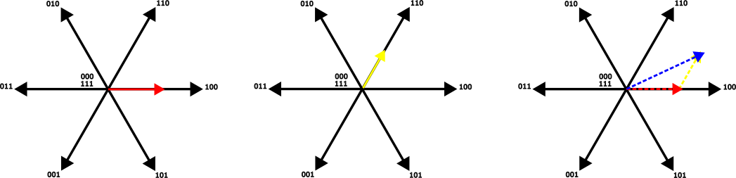
Since voltages are represented as space vectors, the two voltage vectors generated can be added as vectors to generate a resultant space vector.
 |
|---|
| vector addition of 2 space vectors generates a resultant space vector |
This technique can be used to generate any arbitrary voltage space vector using a time weighted vector sum of the 8 space vectors. The VSI was modulating between the voltage space vectors 000, 100, 110, 111 hence the name voltage space vector modulation. The switching sequence to generate the space vector in the above example is summarized in the animation.
 |
|---|
| switching sequence to generate arbitrary space vectors using 8 discrete space vectors |
As seen, the SVPWM (space vector PWM) technique enables a motor controller to supply arbitrary voltages to the motor. During normal operation, the motor controller uses the SVPWM to generate a smooth rotating voltage space vector.
3 phase to 2 phase representation and their use in motor control
One of the advantages of treating motor variables as space vectors is they can be simplified by vector transformation. So, the three vectors that were used in the previous examples can be reduced to two orthogonal vectors. This transformation is called Clarke transform.
 |
|---|
| The space vector generated by the 3 vectors can also be generated by 2 vectors with orthogonal axis (alpha axis and beta axis) and alpha axis aligned with phase A. This 2 axis system is obtained using the Clarke transform. |
The stationary alpha-beta axis reduces the 3-phase sinusoidal variables like voltage, current, back-emf, and flux-linkage to 2-phase sinusoidal quantities.
The space vector can also be generated using 2 vectors with their axis rotating at some frequency. If one of the axis (d-axis) is aligned with the rotor flux position, the other axis (q-axis) will always be orthogonal to the rotor flux. This transform is called park transform.
 |
|---|
| The space vector generated by stationary alpha-beta axis can also be generated by rotating d-q axis |
The current control is implemented after the park transform in the dq reference frame. When the d-axis is aligned with the rotor flux, the current in q-axis directly controls the torque. A PI current controller sets a constant q-axis current to obtain a constant and smooth torque output. Another PI controller sets the d-axis current to zero.
simulation files used in this blog post are available here