[Motor control] What motor parameters are required for sensorless FOC
Sensorless FOC drives are different from hall-sensor drives or sensorless 6-step drives in that sensorless-FOC drives require accurate motor parameters to perform effectively. We will explore which motor parameters that are important, why controllers require accurate motor parameters, and explain the challenges in calculating motor parameters.
Why motor parameters are important ?
In the blog post on introduction to sensorless foc, we explained 2 operations for sensorless-FOC operation: First is estimating the rotor position, second is driving the desired current through the motor winding. Accurate motor parameters are required for both of these operations.
Motor parameters are required for back-emf estimation
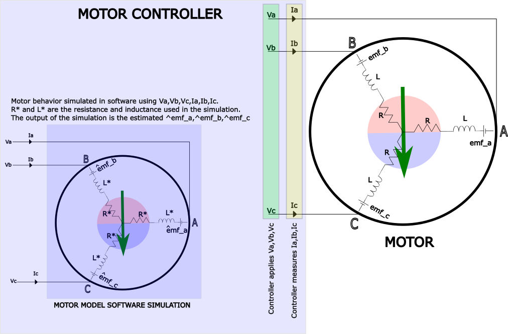
All sensorless-FOC motor controllers use Digital-Signal-Processing techniques called observers to estimate the back-emf. An example of its working is shown in the introduction-to-sensorless-foc blog post. In short, the motor controller uses the knowledge of the motor parameters (this knowledge of motor parameters is called a model of the motor) to calculate the back-emf. The closer the motor model matches the actual motor parameter the closer the estimated back-emf will match the actual back-emf generated in the phase winding.
 |
|---|
| Observers are used in motor control software. Observers simulate the motor behavior and estimate the back-emf generated in the winding. The simulation uses the applied voltage and the measured currents and calculates the back-emf. If the software motor model parameters are close to the actual motor parameters the result of the simulation results in an accurate calculation of the back-emf. |
For effective motor control operation, the controller drives current through the winding such that stator flux generated is orthogonal to the rotor flux position at all times. In a BLDC motor, the back-emf encodes the rotor flux position and the controller infers the rotor flux position using the estimated back-emf. So if the back-emf estimation is incorrect, the error leads to an incorrect estimation of the rotor flux position.
An incorrect estimate of rotor flux position can lead to loss in efficiency since the stator flux will no longer be orthogonal to the actual rotor flux position. In some cases, the error might be large enough to cause an instability in the operation.
If the motor controller uses sensors for angle feedback (like resolver or encoders) this source of error due to incorrect motor parameters are mitigated.
Motor parameters are required for driving the desired current through the winding
After the rotor flux position is estimated (or measured using sensors), the controller attempts to generate a flux orthogonal to this rotor flux position by controlling the current in the phase winding.
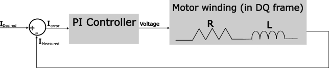
Current control in most devices are implemented using a PI controller. PI controllers do not always require a model of the system they are controlling (in this case the system is the phase winding). The controller gains may be tuned experimentally.
 |
|---|
| Current in motor winding are controlled using standard PI controllers. PI controllers can be tuned precisely using knowledge of the motor phase resistance and inductance. |
Modern controllers however use the model parameters to precisely tune the current controller for specific behaviors. In these methods, the controller gains depend directly on the the motor parameters (resistance and inductance). This method is simpler and faster than experimentally tuning the gains.
How do incorrect parameters affect current control performance ? controllers tuned with incorrect motor parameters can cause undesired behaviors in the performance such as sluggish/slow response to torque disturbance or excessive torque ripples.
Which motor parameters are important ?
To a controller, the motor parameters most important are the motor phase resistance and inductance. If accurate values for these parameters exist the motor controller can work effectively.
All other motor parameters like number of poles, motor constants like Volts/RPM, star or delta winding are not necessary to operate the motor. These details may be used sometimes for an application specific feature like speed control. But these details are almost never required to operate a motor.
Measuring motor parameters
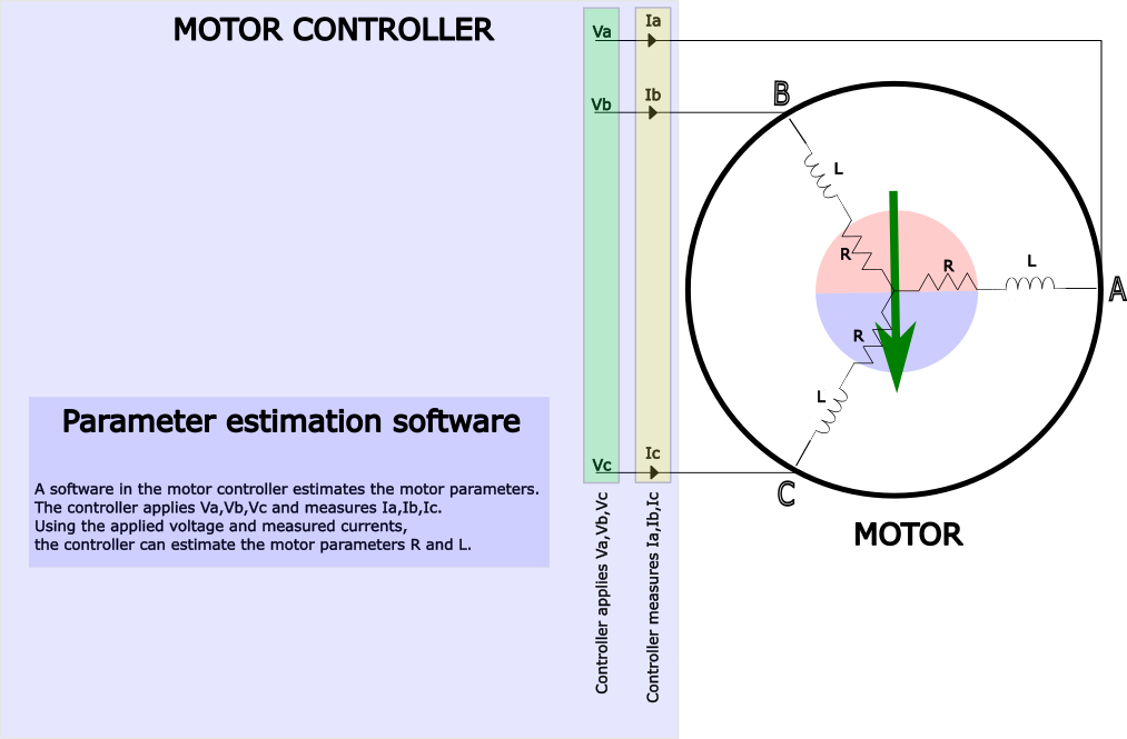
Motor parameters are sometimes found on the motor data-sheet or nameplate. In other cases, the motor parameter can be measured using laboratory equipment. But a more robust method to obtain the motor parameters are using the motor controller itself. The hardware required for accurate motor parameter estimation already exists in most drives and a simple software can be run to quickly estimate the motor parameters.
 |
|---|
| Motor controllers can inject test signals into the motor and measure the response. Using this data, the motor parameters can be accurately estimated without any external tools. Note that the controller assumes all 3 phase of the motor have the same resistance and inductance. It is also assumed that the rotor does not move so there is no back-emf generated that can disturb the estimation process. |
Estimating phase resistance
The phase resistance can be measured through a simple DC injection test. A DC voltage is applied to the motor and the current through the phase winding is measured. The voltage divided by current gives the phase resistance.
Challenges in estimating phase inductance
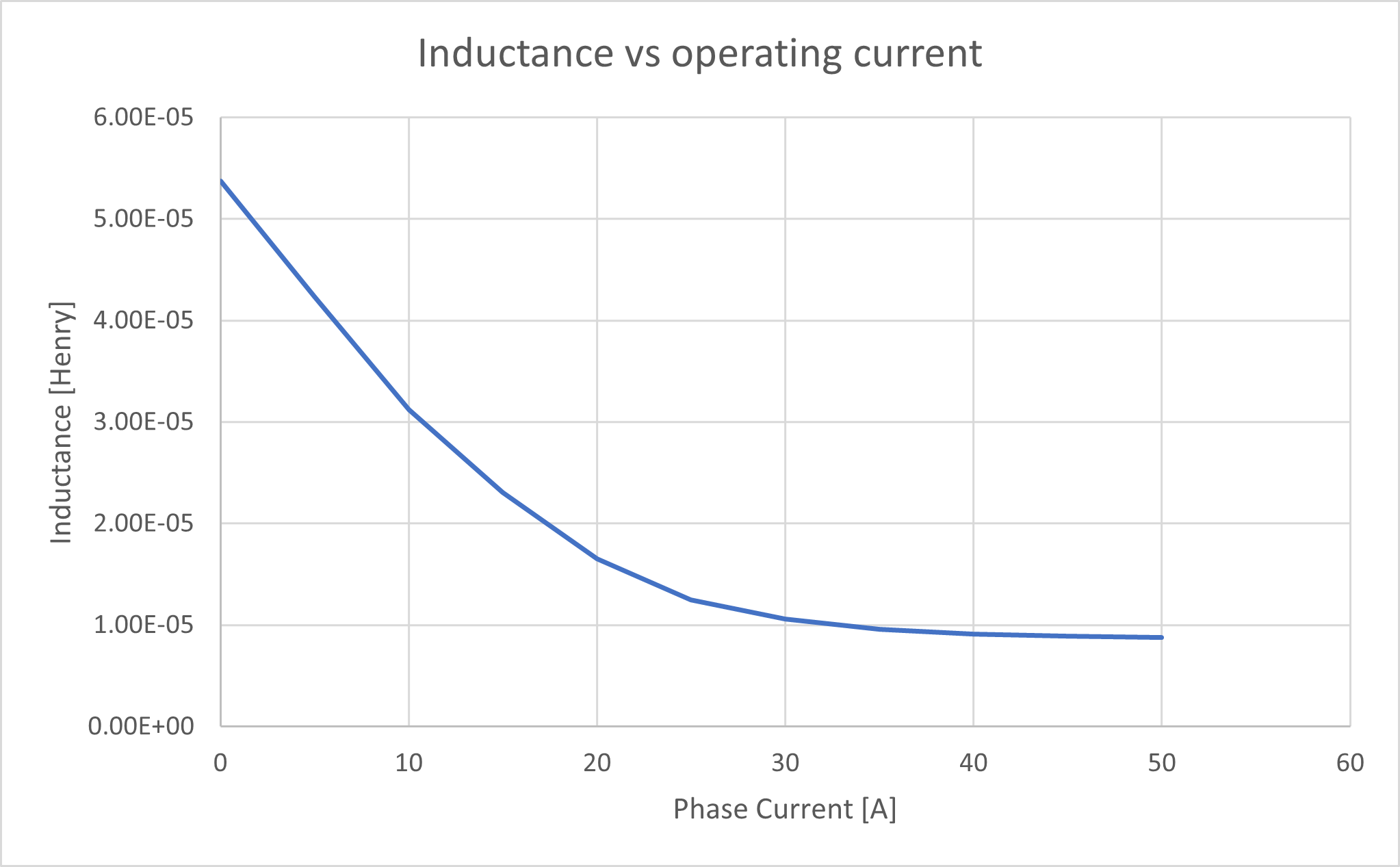
Estimating the phase inductance is a much more involved process. This is because the inductance of the motor is a function of the current in the winding. At higher currents, the inductance of the phase drops due to saturation of the of the material.
 |
|---|
| Simulated drop in inductance as a function of current in the phase winding. Simulation files can be found here |
The injection voltage and the signal processing techniques are more complicated to account for this variation. One technique is to estimate the inductance at different current operating points and generate an inductance profile. This method is used by y-cyc-esc controllers.
Inductance measurement is further complicated by rotor geometry where the inductance can be dependent on the rotor position (for example in I-PMSM). This rotor dependent inductance is sometimes called saliency. [Read more about Saliency here. The y-cyc-esc controller estimates the inductance at 2 different rotor positions (these are called Ld and Lq) to account for this effect.
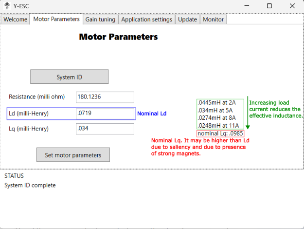 |
|---|
| Screenshot of the y-cyc-esc parameter estimation screen. yoga-cycles-ESC estimates the inductance along 2 axis to obtain Ld and Lq. The drop in Lq inductance as a function of load current is also calculated. In this motor, the inductance drops by 40% for a 11 A current range |
There are many techniques to estimate the inductance of a coil. The simplest technique is to generate a voltage pulse and examine how quickly or slowly the current rises. The controller already has the ability to measure currents, so the analysis can be done quickly in software.
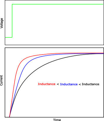 |
|---|
| The response of the current in the phase for a step voltage input gives the controller sufficient data to estimate the inductance. The image shows the differences in current response for differences in inductance |
Note that the controller needs to sample the current measurement fast enough to capture sufficient data of the current response (the technical term for this data is called rise-time). Yoga-cycles-ESC uses similar techniques with different voltage pulses to calculate accurate inductance values.
Yoga-cycles-ESC implements advanced signal Processing techniques to obtain accurate estimates of motor parameters. These motor parameters are then used to auto-tune the controller without any user intervention. The details of the auto-tuning will be covered in a later post.