[Embedded Systems] Sensor fusion example for 6 axis IMU
This project implements a sensor fusion algorithm for orientation estimation using 6 axis IMU sensor. Processing software is used to visualize the orientation estimation. The source code and hardware files are available on github.
Hardware
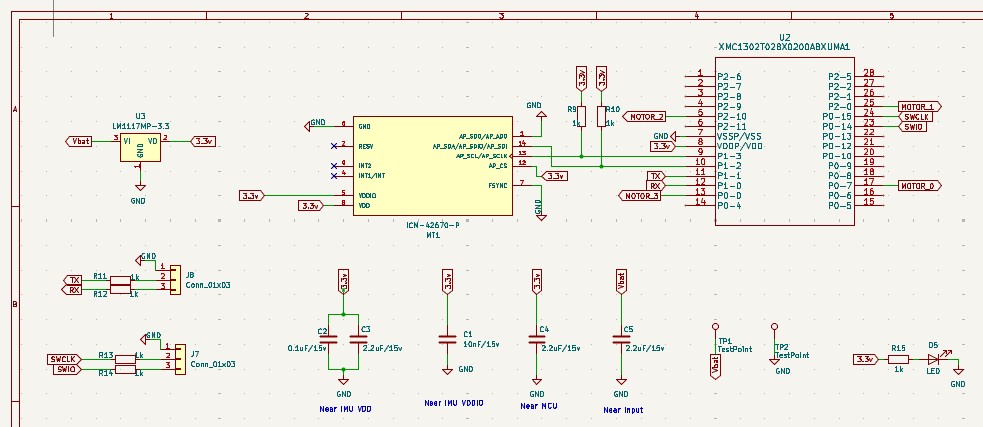
The example will use the Infineon XMC1302 series MCU and the MEMS IMU sensor ICM42670-P. A voltage regulator is used to generate the 3.3V. Note that the example module requires an external power supply and cannot be powered from the USB port.
ICM42670 contains 3-axis accelerometer and 3-axis gyroscope. The sensors can be configured and read out using either SPI or I2C. For this project, the I2C bus will be used. The device also has a temperature sensor and that will not be used in this example.
This XMC1302 series MCU is a standard in most of our devices. We will continue to use it for this example too. In this example, we will configure the hardware I2C to communicate with the sensor and transfer data to the PC through UART.
 |
|---|
| Sample hardware schematic |
Software
Firmware was developed using Infineon’s Dave IDE in C. The Mahony filter will be used to estimate the orientation. The example will implement the sensor fusion algorithm with integer arithmetic as the the MCU does not have a floating point unit (FPU).
MCU to PC communication
The MCU communicates the estimated orientation through UART and baud rate is 115200. The UART communication happens inside an infinite while loop in main() and behaves like a background low priority function.
ICM42670-P settings
The project uses the hardware I2C available in the XMC1302 series MCU and I2C bus operates at 400kHz.
The gyroscope and accelerometer settings are as follows:
- Gyro_mode: low noise mode
- Accel_mode: low noise mode
- GYRO_UI_FS_SEL: 2000 DPS
- GYRO_ODR: 800 Hz
- GYRO_UI_FILT_BW: 180 Hz
- ACCEL_UI_FS_SEL: 16 g
- ACCEL_ODR: 800 Hz
- ACCEL_UI_AVG: 000
- ACCEL_UI_FILT_BW: 800 Hz
Mahony filter
The Mahony filter is a well known quaternion based algorithm to estimate the orientation using MEMS IMU. At a high level, the Mahony filter is a predictor-corrector estimation technique similar to conventional observers. This section briefly explains the working.
gravity vector can be used to determine orientation
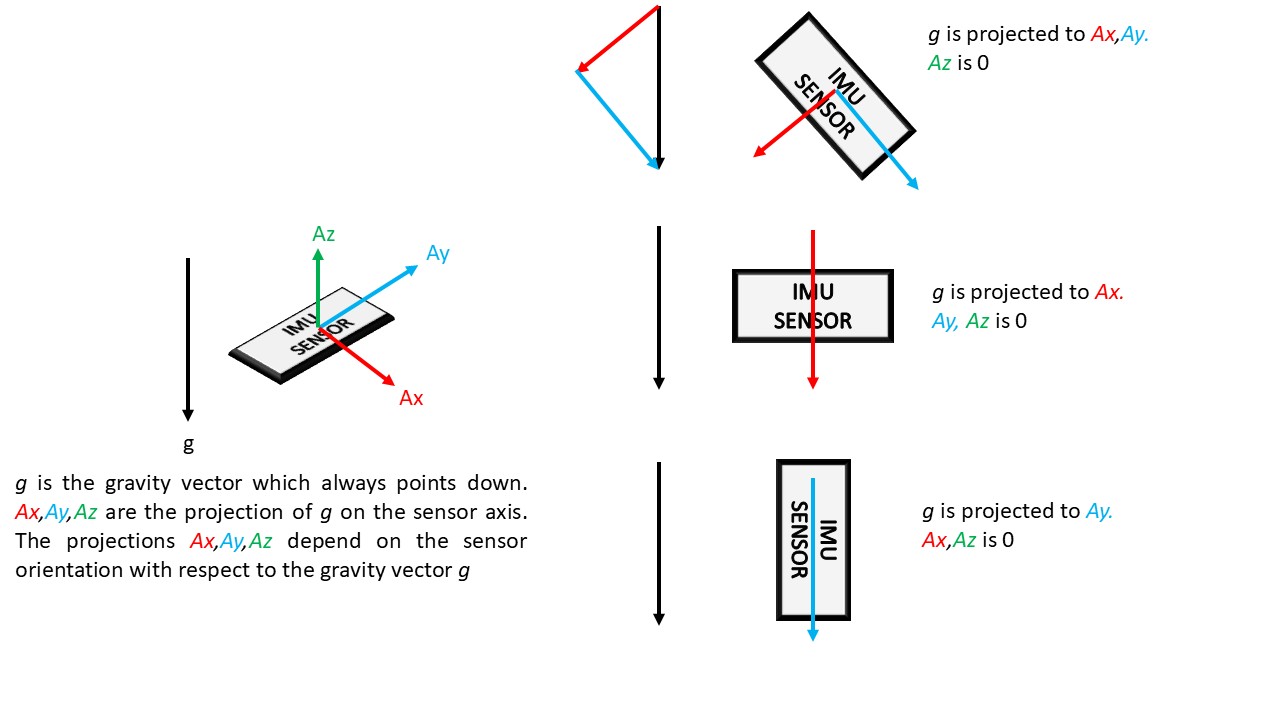
The IMU sensor measures the strength of gravity along its 3 orthogonal axis (this is the accelerometer of an IMU). This measured strength on the sensor axes depend on the orientation of the sensor axes with respect to the gravity vector.
 |
|---|
| the gravity vector is resolved (projected) to the sensor axes. The magnitude of Ax, Ay, Az depend on the sensor orientation |
As the orientation of the sensor changes, the relative strength of measured gravity on the 3 axes of the IMU also change. Thus, the relative strengths measured on the sensor axes directly encode the orientation of the sensor.
angular speed can be integrated to determine orientation
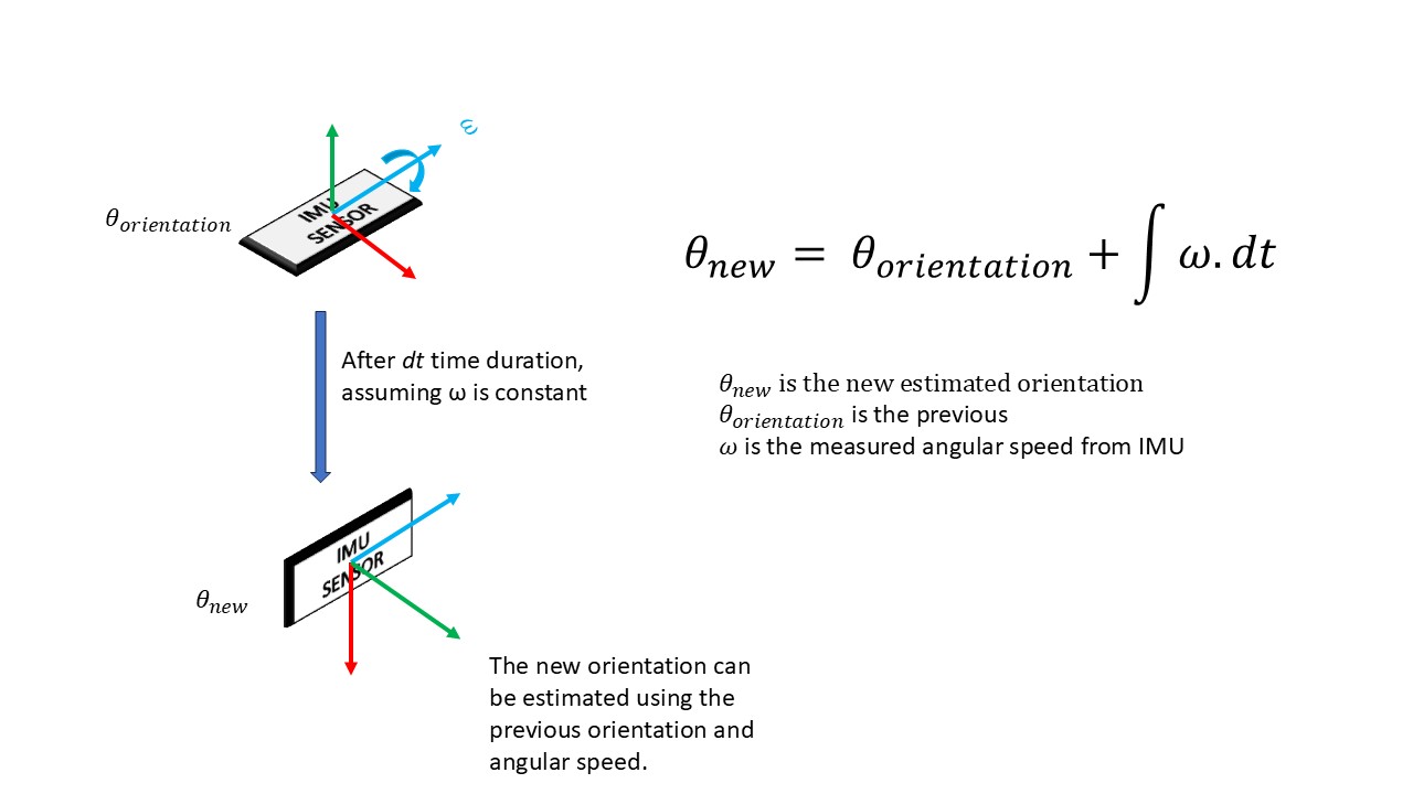
Apart from the gravity measurements, the IMU also measures angular speeds around the 3 axes of the IMU (this is from the gyroscope of an IMU). These angular speeds can be integrated to estimate the angular position (orientation).
If we know the initial orientation of the sensor, and if we measure the angular speed of the sensor, we can estimate the new orientation as the previous orientation + time integral of angular speed.
 |
|---|
| IMU also measures the angular speeds around the axes. These angular speeds can be integrated to estimate the orientation. |
using both methods to determine orientation
Both of these methods has particular strengths and weakness.
The problem with using only gravity measurements: the accelerometer measures not only the gravity, but other accelerations too. So if the device accelerates, we no longer have access to the gravity measurements. It is also not possible to separate the gravity from external acceleration measurements. This property of the accelerometer also makes measurements noisy as it picks up small vibrations which have nothing to do with the device orientation.
The problem with using only gyroscope measurements: Gyroscopes outputs may have a ‘bias’. That means, even when the IMU is not rotating around any axis, the gyroscope outputs a small value. And during rotation, the bias may cause the readings to be higher or lower than the actual speed. As the estimation process involves an integration, each update adds a small error and this process quickly makes the estimation unusable.
The accelerometer does not perform well over short intervals due to noise, but over the long term its values are useful. Gyroscopes don’t perform well on the long term but perform well during short intervals. The orientation estimation algorithm at a high level; It uses gyroscope readings to quickly update orientation and corrects for the long term errors using accelerometer readings.
rotations, vectors, and quaternions
First, the orientation of the IMU is represented internally as a quaternion. Quaternion is one of the ways to represent rotations. Quaternion are represented by 4 numbers. Other ways are using angles like roll-pitch-yaw and 3x3 matrix.
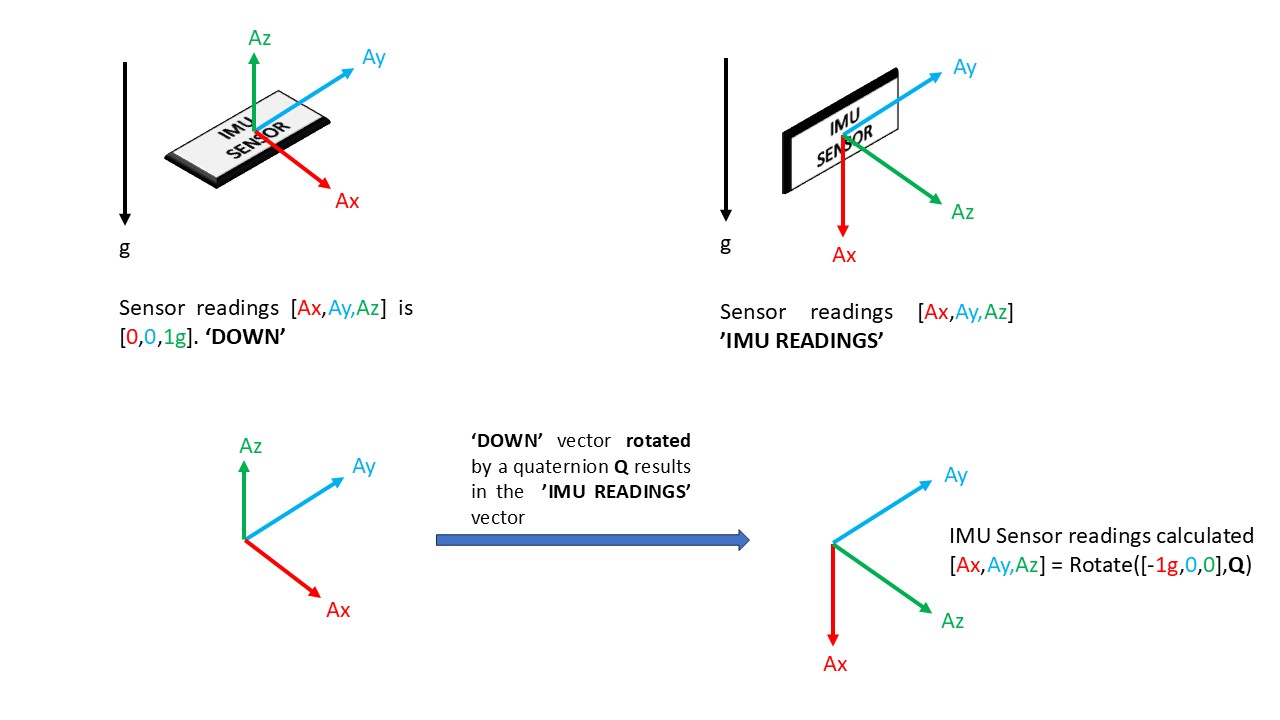
From the previous discussion on using gravity vector to get the orientation, the image visualized how the relative strengths along Ax,Ay,Az change with orientation. Suppose that we define ‘down’ when the relative strengths along sensor axes Ax = 0, Ay = 0, Az = 1g. If the IMU sensor rotates to a new orientation where relative strengths are Ax = -1g, Ay = 0, Az = 0. Both these values can be represented as 3d vectors. The new orientation vector can be written as ‘down’ vector rotated by a quaternion (there are infinite quaternions, this will be addressed later). The quaternion that rotates the ‘down’ vector (0,0,1) to the new vector in IMU sensor readings (1,0,0 in this example) is the orientation quaternion.
To summarize, a quaternion can rotate between 2 vectors. If one of the vectors is a constant vector which is used to represent ‘down’ and the other is the sensor readings in the IMU axes, the quaternion that rotates one to the other can be used to represent orientation.
 |
|---|
| Down vector is fixed. Rotating the down vector using a quaternion Q results in a vector equal to the measured IMU sensor readings. The algorithm attempts to find this quaternion Q. As the IMU sensor rotates, the algorithm also tracks the new quaternion Q that rotates the down vector to the IMU sensor vector |
The previous section also explained how gyroscope readings can be integrated to update the orientation. Gyroscope readings can be integrated to update the orientation quaternion to a new orientation quaternion.
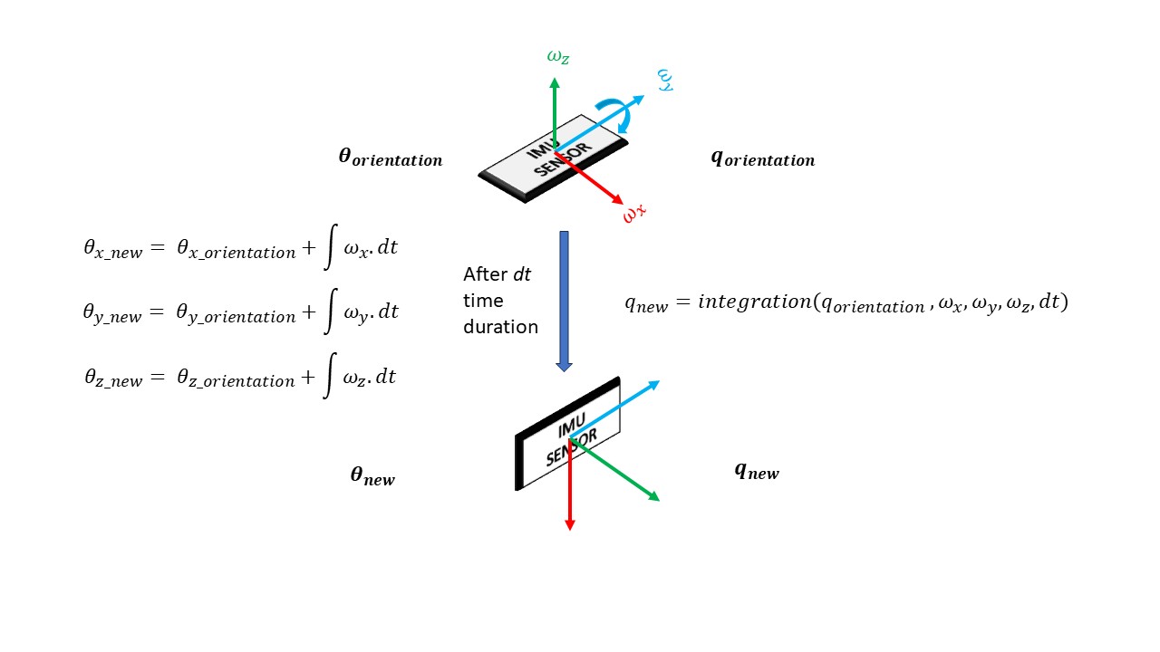 |
|---|
| The orientation quaternion can be updated by integrating gyroscope readings from the IMU. However, the math is not a direct integration but requires some additional steps |
The prediction and correction method
Both the sensors are used to get an estimate of the orientation quaternion. First, the gyroscope readings are used to update the orientation quaternion. Next, the updated orientation quaternion is used to predict the IMU accelerometer vector. The difference (error) between the predicted IMU accelerometer vector and measured IMU accelerometer vector is measured. A fusion algorithm attempts to reduce this difference to ZERO.
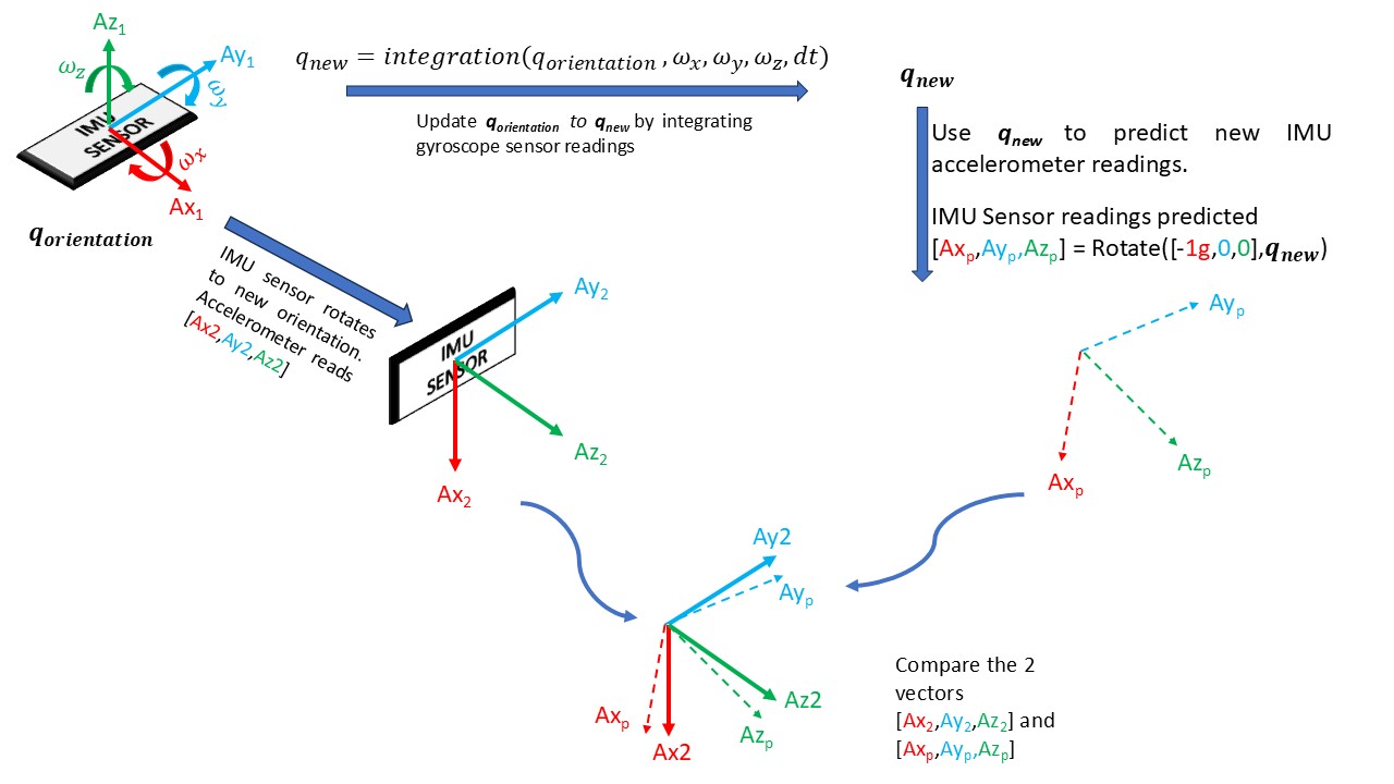 |
|---|
| The gyroscope is used to update the orientation quaternion. The updated orientation quaternion is used to predict the measured IMU accelerometer vector. The fusion algorithm attempts to reduce this difference in predicted to measured vectors to ZERO |
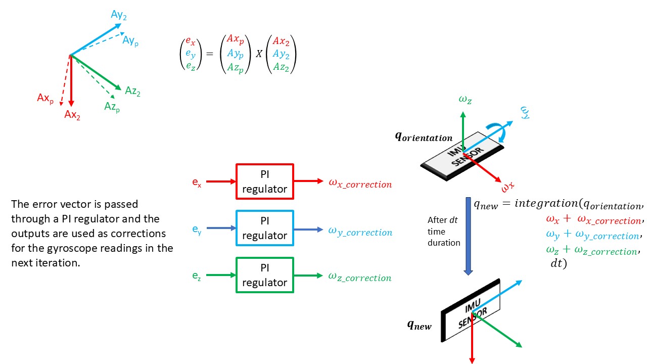
The error described in the previous section is defined as a vector cross product of the predicted accelerometer vector and measured accelerometer vector. So the error calculated is also a 3-dimension vector.
The fusion step involves passing each value of the 3-d error vector through a PI regulator (3 PI regulators for 3 error values). The outputs of the PI regulators are the bias-compensation for the corresponding gyroscope axis and the bias-compensation is added to the gyroscope readings in the next iteration.
 |
This process continues and eventually the predicted IMU accelerometer readings will almost match the measured IMU accelerometer readings and the orientation quaternion has been estimated. The complete flow chart is shown below.
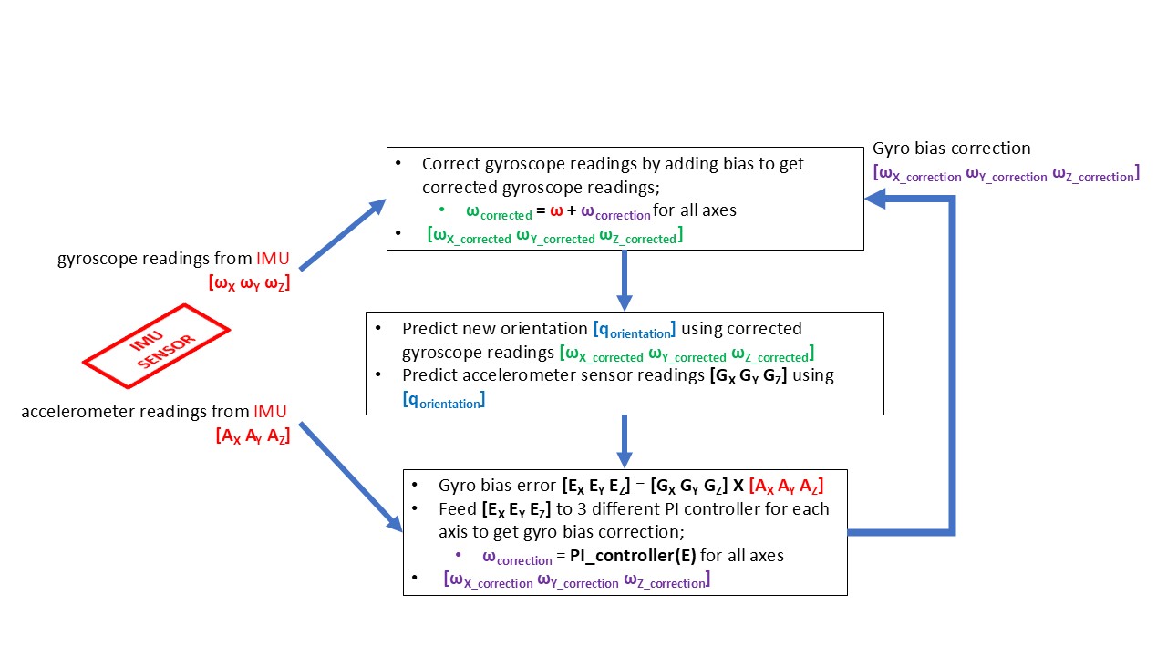 |
|---|
| Flow chart of a Mahony filter implementation |
The 6-axis fusion algorithm uses only the gravity vector to calculate a corresponding orientation quaternion. To fully define the orientation, the algorithm requires another vector. This another vector is usually from a magnetometer (magnetometer measures NORTH as a 3-d vector). Similar to the existing 6-axis algorithm, the 9-axis algorithm should calculate and track the orientation quaternion that rotates TWO constant vectors, DOWN and NORTH, to the measured accelerometer and magnetometer readings. This technique may be covered in a later post.