[Embedded Systems] Sensor fusion example for 6 axis IMU
This project implements a sensor fusion algorithm for orientation estimation using 6 axis IMU sensor. Processing software is used to visualize the orientation estimation. The source code and hardware files are available for download and review.
Hardware
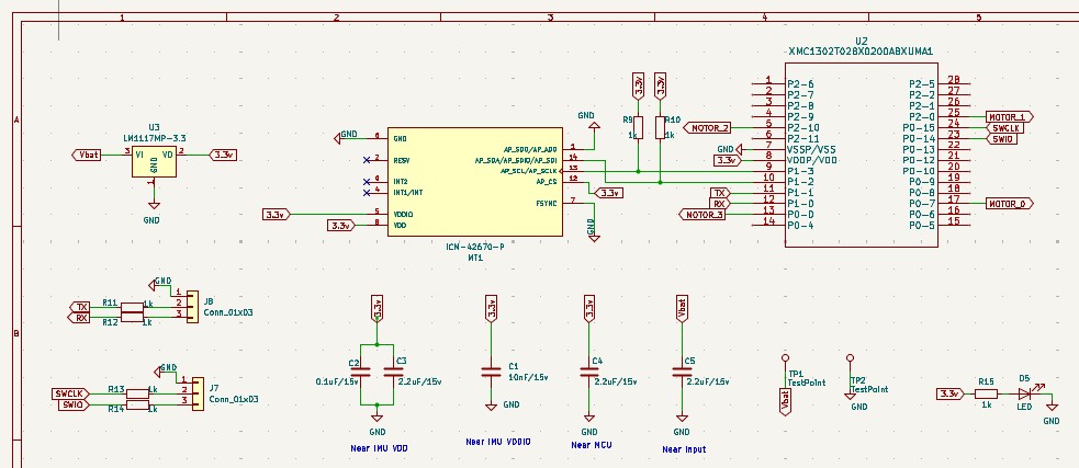
The example will use the Infineon XMC1302 series MCU and the MEMS IMU sensor ICM42670-P. A voltage regulator is used to generate the 3.3V. Note that the example module requires an external power supply and cannot be powered from the USB port.
ICM42670 contains 3-axis accelerometer and 3-axis gyroscope. The sensors can be configured and read out using either SPI or I2C. For this project, the I2C bus will be used. The device also has a temperature sensor and that will not be used in this example.
This XMC1302 series MCU is a standard in most of our devices. We will continue to use it for this example too. In this example, we will configure the hardware I2C to communicate with the sensor and transfer data to the PC through UART. Note that the MCU does not have a floating point unit.
 |
|---|
| Sample hardware schematic |
Software
Firmware was developed using Infineon’s Dave IDE in C.
The algorithm that will be used is the well known Mahony fusion algorithm which uses a PI controller to reduce the gyroscope drift. Because the MCU does not have a floating point unit (FPU), the example will implement the sensor fusion algorithm with integer arithmetic.
MCU to PC communication
The MCU communicates the estimated orientation through UART and baud rate is 115200. The UART communication happens inside an infinite while loop in main() and behaves like a background low priority function.
ICM42670-P settings
The project uses the hardware I2C available in the XMC1302 series MCU and I2C bus operates at 400kHz.
The gyroscope and accelerometer settings are as follows:
- Gyro_mode: low noise mode
- Accel_mode: low noise mode
- GYRO_UI_FS_SEL: 2000 DPS
- GYRO_ODR: 800 Hz
- GYRO_UI_FILT_BW: 180 Hz
- ACCEL_UI_FS_SEL: 16 g
- ACCEL_ODR: 800 Hz
- ACCEL_UI_AVG: 000
- ACCEL_UI_FILT_BW: 800 Hz
Mahony filter
The Mahnony filter is run at 500 Hz triggered by a timer interrupt.
 |
|---|
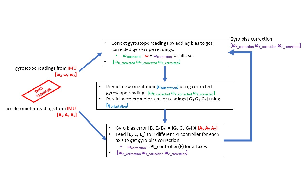
| Flow chart of a Mahony filter implementation |
The Mahony filter is a well known quaternion based algorithm to estimate the orientation using MEMS IMU. At a high level, the Mahony filter is a predictor-corrector estimation technique similar to conventional observers. However, the prediction and correction steps are non-linear operations.
The example project implements the Mahnony filter as in the flowchart. Note that the software does not use floating point numbers. The filter is implemented using only integer arithmetic.